

This post follows up on Drawing vector shapes with <respath> in FSDL (pt. 1) by showing how to draw curved lines using the <respath> element. It finishes up by showing you a free tool that converts SVG paths to FSDL <respath> paths.
Control points and Bézier curves
FSDL 3.0 enables you to create “Bézier” curved paths in the <respath> element. This is done by adding “control points” to a Line segment.
A control handle is a supplementary coordinate pair that effects the strength of a path’s curve. It’s kind of like a magnet that pulls on a path segment, forcing the segment to bend toward the point. The further away the control handle is from the shortest path between the two anchor points, the more the path is bent, and the stronger the eccentricity of the curve.
Here we are going to deal with “cubic” Bézier curves, where each control handle is associated with an anchor point. Cubic Bézier curves are common in computer graphics applications such as Adobe Illustrator and Inkscape.
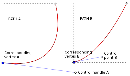
Figure 1 shows two paths in which a control point corresponds with an anchor point. In PATH A, the control handle A is far away from its corresponding anchor point as well as from the Line that joins the adjacent anchor point. It thus produces a curve that is stronger in eccentricity and angle than that in PATH B.
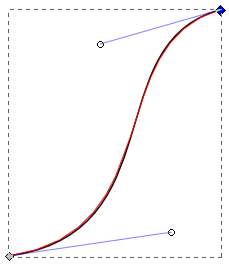
In “cubic” Bézier curves a given path segment can have two control points, each corresponding to one of the two vertices. See Figure 2.
Cubic Bézier curves in FSDL
Let’s draw a cubic Bézier curve like that in Figure 2 in FSDL 3.0 with two control points placed between the two anchor points:
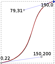
<respath resid='MYpath_2_r' size='640,480' stroke='on' thick='8' spread='off' adjust='0' crop='auto' color='#00BB00'>
Ju:0,220; Cu:190,0,150,200,79,31
</respath>
Here, “Ju:0,220;” represents the coordinate pair for the first anchor point, the one on the bottom left of the figure. The coordinate pairs that follow “Cu:” represent, respectively, the second anchor point, the control handle associated with the first anchor point and the control handle represented with the second anchor point. See Figure 3.
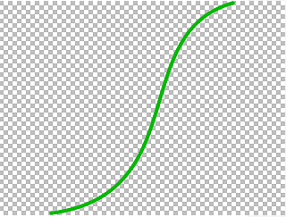
The resulting path on Frogans slide is shown in Figure 4.
To add more curved path segments to this one, you would continue adding “Cu” sets of six coordinates each. Similarly, for adding straight path segments you would add “Li” sets of two coordinates each.
Creating paths using WSYWG software
Because of the complexity of hand-coding vector paths, especially curved ones, it is a good idea to create paths in a graphic editing software that supports vector graphics, such as Adobe Illustrator or Inscape. Once you have created a path that you are happy with, you can export it in SVG format, which you can then convert to FSDL.
Comparing how paths are written in FSDL and in SVG
In both SVG and <respath> in FSDL, paths are written using a series of coordinate pairs. For instance, a path consisting of two vertices connected by a straight Line will be defined with a coordinate pair for each of the vertices.
So, a path plotted in FSDL as…
Ju:0,100; Li:100;0
…is equivalently plotted in SVG as…
M 0,100 L 100,0
… where the coordinates following “M” represent the first anchor point in the path and those following “L” represent the second anchor point.
For the path illustrated in Figures 2, 3 and 4, the FSDL coordinates written as…
Ju:0,220; Cu:190,0,150,200,79,31
… would be written in SVG as…
M 0,220 C 150,200 79,31 190,0
… where “C,” indicating a cubic Bézier path segment, is followed by the coordinates for the control handle associated with the first anchor point, then by the coordinates for the control handle associated with the second anchor point and, finally, by the coordinates for the second anchor point.
As you can see, in SVG, the second anchor point is written after the two control points whereas, in FSDL, the second anchor point is written before the two control points. Note also that, in SVG, the coordinate pairs are separated by spaces, whereas in FSDL, commas are used.
While a key difference between <respath> in FSDL and SVG is in the placement of the second anchor point in a curved path segment string, there are other notable differences:
-
SVG allows for decimal values, such as “10.251” or “0.3,” whereas FSDL allows only integers.
-
SVG allows for relative coordinates in a path. For instance, if the uppercase “C” or “L” is replaced be a lowercase “c” or “l,” then the following coordinates will not be absolute, but rather they will be relative to the coordinates of the last anchor point in the previous segment.
-
SVG allows for multiple path segments to be written as a single string, for instance “C 25,70 50,95 120,60 173,35 72,49…,” whereas in FSDL, path segments are written in separated group strings.
Using Inkscape as an SVG editor
Inkscape is an OpenSource cross-platform WSIWYG SVG editor. It allows you to create original SVG artwork using a graphic interface. But it also provides an XML editing module for editing your work in SVG code (Edit > XML Editor… or Shift+Ctrl+X). This is useful for preparing vector paths for FSDL. That is to say, you can prepare a path in Inkscape, copy its SVG code from the XML editing module and, after some modification, paste them into an FSDL <respath> element.
Set your Inkscape SVG output preferences to minimize the modifications that you’ll have to make to your code. Go to File > Inkscape preferences > SVG output:
-
Make sure that “Allow relative coordinates” is not checked. This way, all coordinates will be based on their absolute values, Just Like in FSDL.
-
Make sure that “Force repeat commands” is checked. This way each path segment will be written as its own coordinate group, Like in FSDL.
-
Set “Numeric precision” to “3” and “Minimum exponent” to “-1” so that most of the coordinates will be integers, as required in FSDL (if you set “Numeric precision” to “2” it will round out all decimals, but also unnecessarily distort your image; it’s better to keep it at “3” and to clean up the remaining decimal values by hand).
Note that many graphics applications, Like Illustrator and LibreOffice Draw, can export in SVG format, but don’t necessarily offer the capacity to edit your work directly in SVG. So if you prefer to create your artwork in these other applications, you can benefit from Inkscape for preparing your paths for conversion to FSDL format.
A free SVG to FSDL conversion tool
If you want to convert it to FSDL by hand, most of the work is going to involve getting your coordinate pairs in the right order. But what if you’ve drawn a fairly complex vector shape with tons of anchor points and control points?
The good news is that simple tools can be developed for helping you do this. The GREAT NEWS is that it has already been done by the OP3FT using JavaScript and HTML that you can download here or simply use it online here.

The svg2respath tool works in your Web browser. When you open it you will see that it has two text fields: One (SVG:) where you paste in the SVG coordinates for the shape you’ve drawn and the other (<respath>:) where the tool puts the FSDL <respath> coordinates for the same shape when you click “Convert.”
Before using this tool, use Inscape to make sure that your coordinates are all absolute, and that each path segment is written as its own group of coordinates. Again, you can do this by setting Inkscape’s SVG output preferences as shown in the previous section.
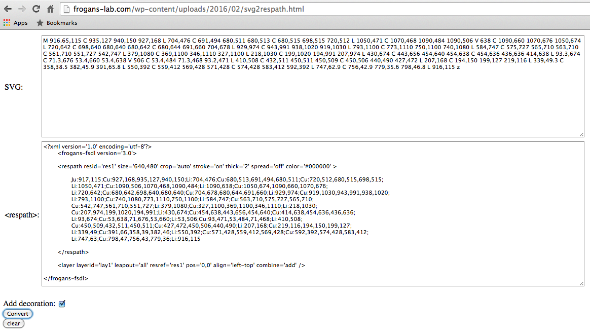
The svg2respath tool will even create an FSDL document that presents this shape in a layer. All you have to do is to check the “Add decoration” box before you click convert.
To view this FSDL file in Frogans Player for Developers, just copy this output (make sure that “Add decoration” has been checked), paste it into a raw text document, save the document as “home.fsdl” and then save it into a new folder in your Frogans Player’s “test” folder. Then, in Frogans Player for Developers, open your site as “test*” followed by the name of your folder.
Your slide should show a complex path image that looks like Figure 7:
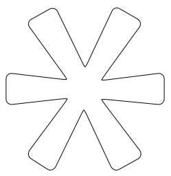
And since is drawn in FSDL 3.0, you can modify it in FSDL 3.0. For instance, you can change the thickness and color of the stroke, or you can give it a fill, instead of a stroke. You can even change the placement of the anchor points and the control points, even though you will probably want to do that in Inkscape or in Illustrator.
Click here for more about using the Frogans Player for Developers alpha.
Update 18 May 2017
With the latest Inkscape I noticed that the “Z” character in the SVG output is in upper-case. The svg2respath tool doesn’t like that and returns errors. To fix this, simply replace all the upper-case “Z”s with lower-case “z”s.
Leave a Reply